Dinos and Insects and Cuttle, oh my
- Phil Barrett
- Feb 4, 2022
- 6 min read
Updated: Aug 19, 2023
On a slightly different topic, I've been having fun with a new CAD app called Cuttle. Currently in beta, it is cloud based (but don't hold that against it). It has a different twist to CAD that I find refreshing. Everything is component based and this allows you to create parametric models with ease. I've been on the internet since the very early days and one of the things I have been saving are the cut diagrams for those "plywood dino puzzles" (for lack of a better description) that use flat pieces that connect together via slots. I always wanted to make one on my CNC machines but the diagrams were all set up for a specific slot width so you had to cut it at just the right size to work with the plywood (er, sheet material) you have. You can't just resize the cut diagram arbitrarily and plywood thickness varies considerably (when is 1/4" not 1/4"? In a lumber store...).

For the TL;DR crowd, skip to the end for some plans that you can modify with ease and download to cut.
"This can't be hard to fix", I thought while looking at my growing collection. I want to resize the cut diagram and slot size independently. Parametrics to the rescue! Or so I thought. Basically 20th century CAD ignored parametric design. Smile turned to frown. No joy. We started seeing parametrics entering the tools kits around 20 years ago. With each new CAD application, I checked it out. Sketchup, Fusion360, VCarve, FreeCAD, ... For various reasons, none of them made it feasible. You could do it but it wasn't easy. Either their parametric model was not flexible enough or they didn't handle the vector outlines of up to one hundred slots and complex outline shapes (aka vectors). Until I tried Cuttle. Yes Joy!
Cuttle uses a component model that allows easy parametrization. It has a way to separately define the slots from the outlines and then combine them via a "boolean difference" modifier. Essentially cutting the slots. It also makes it easy to create a simple generator that you can set the size of the sheet you want to cut and the width of the slot and download a vector file (SVG, scalable vector graphics format) for use with your CAM tools for a CNC Router or Laser Cutter.
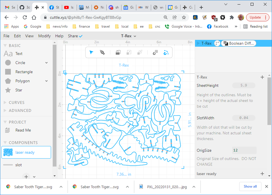
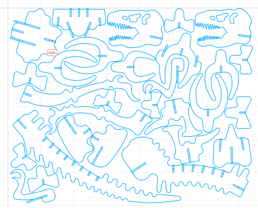
Let's look at how this works. Using the above Tyrannosaurus Rex model, here is the diagram I had saved. It was in a DXF format which I think stands for Don't eXpect Finished. Anyone who has tried to use DXFs in CAD programs understands that. It needed a lot of massaging to get the vectors into a set of closed outlines. I used VCarve Pro from Vectric to do the manipulations. It has really great vector operations but just about any tool that deals with vectors will work. Exported it as an SVG. Having closed vectors is key to the process.

Once I had the vectors set up, I created a new Cuttle project, called T-Rex. Imported the SVG file into a component I named laser ready. It shows up a group of shapes in Cuttle parlance. I created a component called slot and dragged a Rectangle from the left hand panel into it. Additionally, I created 2 parameters for the main project (aka Global Parameters) - SheetHeight and SlotWidth. Click on the + button next to the project name in the right hand panel to create parameter. The sharp eyed will notice another parameter called OrigSize, more on that later. You can add comments to the parameters to help people understand how they are used. More on this also. Next, I dragged a slot component over every slot in vector shapes in the laser ready component and then aligned the slot components with the slots in the outlines. Having the slots in the original vectors makes it easy to align the new slot components.

To make it parametric, I modified the slot component's transform to take into account the parameters I had defined above. I wanted to be able to change the size of the vectors (ie the overall puzzle's size) so need to undo the resultant resizing of the slot width. Cuttle transform deals in scale for resizing. Note that it only changes the Y value of the scale transform.

We will use Boolean Difference to cut out the slots for the final, downloadable vectors. But we first need to fix a problem with this approach - there are still slots in the original vectors. These will interfere with our boolean difference modifier when the slot component is too narrow. So, we need to remove the slots from the original vectors. You can do this in Cuttle but VCarve is super easy and fast so I used it to generate an SVG with no slots. Back in Cuttle, opened the laser ready component and imported the no slot SVG. If it doesn't import with the same scale as the one with slots, you can adjust it so slots and no slots are the same size. Then drag the no slot one so both SVGs are perfectly aligned (it should snap into place) and delete the one with the slots.
Here is what you will end up with.

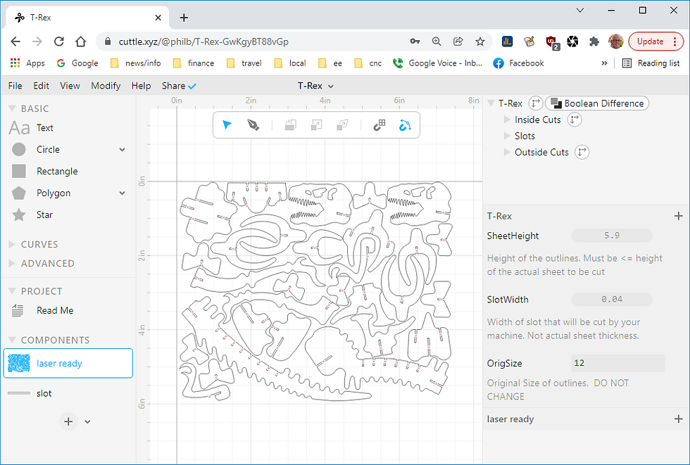
Now we need to reorganize the various components so the Boolean Difference modifier can work. This entails separating the slots, internal cuts (like eyes) and external cuts (all the part outlines) into three groups. Multiselect the items you want to group and press <ctrl>-g. On the right hand side of the screen you will see a list of all the shapes you are using. Drag the internal cut group above the slots in the list and the external cut group to the bottom of the list. Now, we need to create a group with all the shapes in it. You can draw a rectangle around all the shapes on the canvas (center panel) and press <ctrl>-g. Finally, apply the Modify/Boolean Difference to the top level group and you will see the slots being "cut". Here is what you will see.

Now, we need to set up the ability to change the size of the cutout sheet via the SheetHeight parameter. This uses the parameters SheetHeight and OrigSize we defined earlier. Because a component's size is defined by scale, OrigSize is necessary to calculate the scale value for the transform of the laser ready component. The value of OrigSize should be the actual height of the group when the scale parameters are set. Or, technically, the size of the object when scale has a value of 1.

To finish it up, we create the Read Me section. Open the Read Me part of the project (left hand side panel) and add the laser ready component. Click on the "Click here..." line and select the component option. You can also add text, images and formatting. Note that the comments you added to the parameters show up here. This makes for a friendly interface. And last but not least, we need to share our creation! Click on the share menu and it select either Unlisted or Public depending on how you want to share it.
Using Cuttle has been a lot of fun. It is a powerful new application that allowed me to overcome the barriers to making these plans parametric. It is still in Beta and evolving. There are a few rough edges but the Cuttle team is working hard to fix them. They are very responsive on the discord server. Thanks to Toby and Ryan for answering all my questions - stupid or not.
Here is a list of the ones I have created and shared.
Most are set up to cut on a laser cutter. If you want to make really large ones on a CNC router, you may need to edit the downloaded SVG to move the closed vectors farther apart. Don't forget to keep any internal cut outs like eyes with the shape they reside in when you move it. You may want to add tabs in your CAM program though that is kind of a pain (both making the tabs and cleaning them up later). A downcut spiral endmill may pack the kerf with chips enough to prevent moving. Do not use an upspiral bit because it will pull the parts up.
I will be adding more to the list. Check my Cuttle page to see what's avalable.
About Me.

I'm Phil Barrett, a long time CNC enthusiast. I run a small company, Brookwood Design, that makes several breakout boards for grblHAL and love to help people get the most out of their CNC machines.


Black and White Cool Abstract Wallpapers and Backgrounds