Building the Avid Pro: Part 4 - Planning the electronics case.
- Jun 22, 2021
- 3 min read
Updated: Dec 16, 2023
One of my goals for this project is to have a well designed electronics cabinet that is neatly organized and allows easy maintenance. It needs to have good airflow to minimize heat related problems. I looked at a number of different electronics set ups and, frankly, the Avid Plug and Play offering looks really well thought out and worthy of emulation. What I am showing you here is a preliminary layout. I will continue to tweak and fuss over it until I actually commit to cutting holes in metal.
Once I knew what parts would be required, I created a CAD drawing of each component and laid them out to see how big a box I would need. While this may seem like a lot of work, you don't need overly detailed models to figure out the space requirements. And, doing it in CAD make it easy to try different ideas. After playing with the model a bit I decided that I needed around 300 square inches of panel space to mount the components. Looking at various cases, I found one from Bud Industries that looked pretty good. It is the model SNB-3746 which is 16"x20"x8" which I also modeled in CAD. The walls and door are made of 16 ga (1.5mm) steel. The door has a gasket for sealing but I will be punching holes for fans so that wasn't important. Oddly enough, it looks strikingly similar to the Avid Plug and Play case. It has a 14ga (2mm) steel removable internal panel that allows you to assemble and test your system outside the case. It wasn't cheap but definitely worth it.
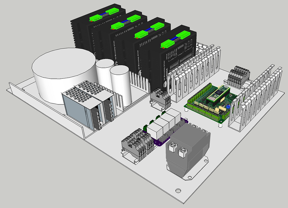
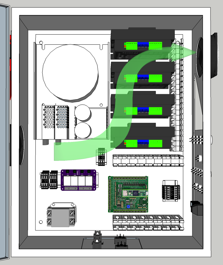
With the system case chosen, I modeled the removable panel and played with several layout ideas for the components. I also needed to needed to take into account the fan openings, connector panels, switches, EStop, power inlets and so on. After a fair amount of back and forth, I came up with something that seems to work. I will continue to tweak it a bit.

The main power switch and the "push" fan are located on the side that will face forward. I'm a fan of the paddle switches that very easy to turn off and also take a very firm, deliberate push to turn on. This switch controls a contactor that will supply power to the system and the VFD/Spindle.

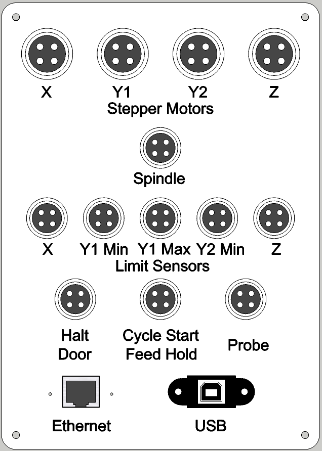
Along the way I also drew up a first cut at the connector panel. I had originally though I would cut holes in the box for each connector, I quickly realized that would be troublesome - one mistake and the case is ruined (or, perhaps, permanently ugly). In looking at several cases out there, it became clear that I should create a separate panel out of aluminum and cut a large hole in the case for the panel. The panel itself would cover up any minor mistakes in cutting the case and if I botch the panel itself, I can just toss it and start over. Plus, I could cut the panel on a CNC machine and even label it. More on the labeling process in a future blog entry.

The Avid case has another good idea that I borrowed - support for relay switching of external 120 VAC. This avoids having to use fuses or circuit breakers. It also removed external device power draw from the system calculations. In this case, I have 2 inlet/outlets. One for the spindle and one for the dust collection system. I will probably not need the Spindle relay and may repurpose for a coolant or vacuum pump.
I have planned on placing this panel on the bottom of the case though may move it to the side.
One of the things I worry about is getting good airflow in the case. Having built a number of PCs, I was aware of the issues and decided to use 2 fans in a push-pull arrangement. I found 80mm 240VAC fans that seem to fit my needs. While they are a bit small, 2 of them working together should be OK. I set it up to have the intake on the mid left side of the case and the outflow on the upper right. The heat generating components are in the upper half of the case so the two fans should keep things fairly cool. I will monitor the temperature in the case and, if necessary, will move to bigger fans.
So, that's it for another session. Next, I will start building up the electronics on the removable internal panel and testing them before cutting up the case.
About Me.

I'm Phil Barrett, a long time CNC enthusiast. I run a small company, Brookwood Design, that makes several breakout boards for grblHAL and love to help people get the most out of their CNC machines.


Waiting for part 2 for the case build. Did you ever think about using different connectors for the limit switches and steppers. I would probably plug the limit cable into the steppers 😯 Edit: I see you are using different size connectors for the limits and steppers.